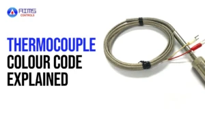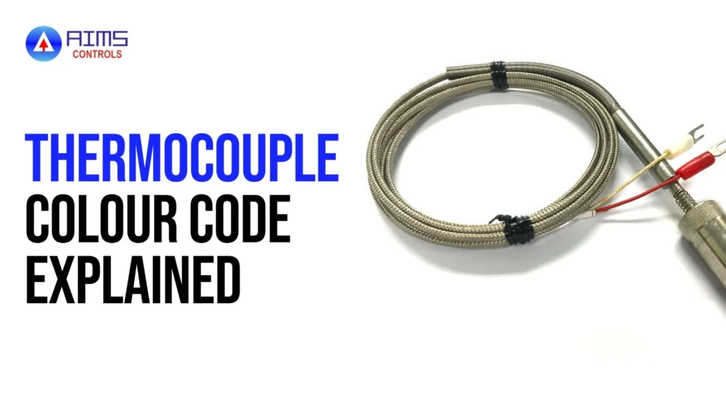
Every thermocouple relies on two dissimilar metal conductors, and connecting them the wrong way round can quietly ruin a temperature reading. The thermocouple colour code is the quickest way to identify wire type and polarity before installation. However, the color code of a thermocouple depends on the standard in use. North American ANSI conventions and the international IEC system assign different colors to the same thermocouple type, which is a common source of wiring errors. This guide explains how the colors work, provides a thermocouple colour code chart for Types K, J, T, E, N, R, S, and B, and shows how to avoid costly mistakes on site.
What Is a Thermocouple Colour Code?
A thermocouple colour code is a system of insulation colors that identifies the thermocouple type and the polarity of each conductor. Each type uses a specific pair of alloys, and the insulation color tells you which alloy pair you are handling without cutting or testing the wire.
The code works on two levels. The individual conductor insulation identifies the positive and negative legs. The outer jacket, which covers both conductors in a duplex cable, identifies the thermocouple type and, in most cases, whether the cable is thermocouple wire, extension wire, or compensating cable.
The important point is that colors are not universal. A color code is only meaningful once you know which standard the cable was made to. Reading a white wire as positive on an IEC cable, for example, will give you the opposite of what the same color means on an ANSI cable.
Thermocouple Colour Code Chart by Type

The table below lists conductor colors for the eight common letter-designated types. The jacket columns show the outer sheath color normally used on extension or compensating cable under each standard.
| Type | ANSI conductors (+ / −) | ANSI jacket | IEC conductors (+ / −) | IEC jacket |
| K | Yellow / Red | Yellow | Green / White | Green |
| J | White / Red | Black | Black / White | Black |
| T | Blue / Red | Blue | Brown / White | Brown |
| E | Purple / Red | Purple | Violet / White | Violet |
| N | Orange / Red | Orange | Pink / White | Pink |
| R | Black / Red | Green | Orange / White | Orange |
| S | Black / Red | Green | Orange / White | Orange |
| B | Gray / Red | Gray | Grey / White | Grey |
Note: Types R and S share the same colors, as do the extension cables for these two noble-metal types. Because the colors cannot separate them, always rely on cable markings and documentation to confirm the exact type.
Type K, J and T Thermocouple Colour Codes
Types K, J, and T are the most widely used base-metal thermocouples, and they are the types people search for most often. Each has its own alloy pair, temperature range, and typical use, so the sections below cover them separately. For a broader comparison of the different types of thermocouples, including their benefits and limitations, see the different types of thermocouples guide.
Type K Thermocouple Colour Code
The Type K thermocouple colour code under ANSI is a yellow positive conductor and a red negative conductor, with a yellow jacket. Under IEC, the positive conductor is green, and the negative is white, with a green jacket.
Type K uses Chromel (nickel-chromium) as the positive leg and Alumel (nickel-aluminium) as the negative leg. It works across a wide range, from roughly −200 °C to about 1,250 °C, and is resistant to oxidation. That makes it the general-purpose choice for furnaces, kilns, exhaust systems, heat treatment, and many process lines.
Type J Thermocouple Colour Code
The Type J thermocouple colour code under ANSI is a white positive conductor and a red negative conductor, with a black jacket. Under IEC, the positive conductor is black, and the negative is white, with a black jacket.
Type J pairs iron (positive) with constantan (negative). It is typically used from 0 °C to around 750 °C. Because iron rusts in moist conditions, it suits dry, reducing, or vacuum environments. Common uses include plastic processing, injection moulding machines, packaging equipment, and older industrial installations.
Type T Thermocouple Colour Code
The Type T thermocouple colour code under ANSI is a blue positive conductor and a red negative conductor, with a blue jacket. Under IEC, the positive conductor is brown, and the negative is white, with a brown jacket.
Type T pairs copper (positive) with constantan (negative). It performs well at low temperatures, from about −200 °C to roughly 350 °C, and tolerates moisture better than Type J. Typical applications include cryogenic work, refrigeration, food processing, laboratories, and HVAC monitoring.
ANSI vs IEC Thermocouple Colour Code Standards
ANSI MC96.1 and ASTM E230 govern the system used mainly in North America. IEC 60584-3 defines the system used across Europe and most international projects. Older national standards, such as former British and German codes, still appear on legacy plants, so existing installations may follow neither current standard.
The two systems follow different logic. ANSI always makes the negative conductor red and varies the positive color by type. IEC always makes the negative conductor white and generally matches the positive conductor to the jacket color.
| Type | ANSI (+ / −) | IEC (+ / −) | Key difference |
| K | Yellow / Red | Green / White | Negative is red in ANSI, white in IEC |
| J | White / Red | Black / White | White is positive in ANSI, negative in IEC |
| T | Blue / Red | Brown / White | Completely different colors for both legs |
Type J is the most hazardous case. A white wire is the positive conductor under ANSI and the negative conductor under IEC, so mixing the standards can reverse polarity without any visible warning.
How to Identify Thermocouple Positive and Negative Wires
Polarity identification starts with the standard. On ANSI cable, the red conductor is always negative. On IEC cable, the white conductor is always negative. The remaining conductor is positive in both systems.
When the standard is unclear, work through these checks in order:
- Read the markings – Many cables carry a printed type designation, standard reference, and conductor information on the jacket.
- Check the specification – The datasheet, purchase order, or cable drawing confirms the standard and type.
- Compare with the connector – Standard thermocouple connectors are usually color-matched, and miniature connectors use a wide blade for the negative pin.
- Use a magnet as a secondary check – The positive iron leg of a Type J is strongly magnetic, and the negative Alumel leg of a Type K is mildly magnetic. Copper in Type T is not magnetic.
A magnet test only indicates the alloy. It does not replace documentation, so use it to support a conclusion rather than to reach one.
Thermocouple Extension Wire vs Compensating Cable Color Codes
Thermocouple extension wire and compensating cable both carry the signal from the sensor to the instrument, but they are built differently.
Extension wire uses the same alloys as the thermocouple, or alloys with nearly identical thermoelectric properties. It is used for base-metal types such as K, J, T, E, and N, and is marked with an X, such as KX or JX. Compensating cable uses cheaper alloys that match the thermocouple’s output only over a limited temperature range. It is used mainly for noble-metal types such as R, S, and B, where long runs of platinum-based wire would be costly.
Both follow the same conductor and jacket color conventions as the thermocouple type they serve, which makes the printed markings essential for telling them apart. Using the wrong cable introduces errors because the cable generates its own voltage along the run. This is why the cable must match the sensor type and the instrument input. Where the signal is converted close to the sensor, temperature transmitters reduce the length of thermocouple cable needed.
Common Thermocouple Wiring Mistakes to Avoid
Most thermocouple errors come from installation rather than the sensor itself. These are the mistakes that appear most often:
- Reversed polarity – Swapping the positive and negative leads can cause readings that move in the wrong direction or show large errors.
- Mixing ANSI and IEC standards – Connecting an IEC cable to an ANSI instrument, or the reverse, can invert polarity, especially on Type J.
- Using the wrong extension cable – A Type K extension cable on a Type J sensor produces an incorrect signal that no calibration can correct.
- Loose or corroded connections – These add resistance and create unwanted junctions, causing unstable or drifting readings.
- Faded or damaged insulation – Heat, UV light, and chemicals can fade colors until they can no longer be read. Replace or re-identify any conductor you cannot confirm.
Each of these errors changes the voltage the instrument reads, and the resulting temperature value can look plausible while being wrong. A quick verification of type and polarity at commissioning avoids that risk.
How to Choose the Correct Thermocouple Wire
Start with the thermocouple type, because the wire must match it exactly. Then work through the remaining factors:
- Operating temperature – Check that the wire and insulation suit the highest temperature at the sensor and along the cable route.
- Wiring standard – Choose ANSI or IEC to match the instrument, existing wiring, and project specification.
- Insulation material – PVC suits low temperatures, PTFE and fibreglass handle higher heat, and ceramic fibre or mineral insulation handles extreme conditions.
- Environment – Consider moisture, chemicals, abrasion, vibration, and electrical noise. Shielded or twisted-pair cable helps in noisy plants.
- Instrument compatibility – Confirm that the controller, indicator or transmitter is set to the same thermocouple type.
When selecting the sensor and cable together, it helps to review the range of industrial thermocouples available and match the cable to the chosen type and standard.
FAQs About Thermocouple Colour Codes
What is the standard color code for thermocouples?
There is no single global standard. ANSI/ASTM E230 is used mainly in North America, with red always negative, while IEC 60584-3 is used internationally, with white always negative.
What is the color code for a Type K thermocouple?
ANSI Type K wire is yellow (positive) and red (negative) with a yellow jacket. IEC Type K wire is green (positive) and white (negative) with a green jacket.
What is the color code for a Type J thermocouple?
ANSI Type J wire is white (positive) and red (negative) with a black jacket. IEC Type J wire is black (positive) and white (negative) with a black jacket.
What is the color code for a Type T thermocouple?
ANSI Type T wire is blue (positive) and red (negative) with a blue jacket. IEC Type T wire is brown (positive) and white (negative) with a brown jacket.
What is the difference between ANSI and IEC thermocouple colour codes?
ANSI always uses red for the negative conductor and a different positive color per type. IEC always uses white for negative, and the positive conductor matches the jacket color.
Is the red thermocouple wire positive or negative?
Under ANSI, red is the negative conductor on every thermocouple type. Under IEC, white is negative instead, so confirm which standard applies before wiring any red-coded lead.
How can I identify a thermocouple without color coding?
Check any tag, datasheet, or cable marking first. If none exists, a magnet test and a calibrated meter can help, but results are indicative only and should be verified.
Can different thermocouple wire types be connected?
No. Each type needs matching thermocouple wire or extension cable of the same type throughout. Mixing types introduces additional junctions that generate incorrect voltages and produce inaccurate temperature readings.
Are thermocouple extension wires color-coded?
Yes. Extension and compensating cables follow the same standard colors, with jackets usually matching the thermocouple type, and carry markings such as KX or JX.
What happens if thermocouple wires are reversed?
Reversed polarity produces readings that fall as temperature rises or show large errors, because the voltage opposes the instrument’s expected direction. Correct wiring before relying on any measurement.
Get Thermocouple Wiring Right from the Start
Correct thermocouple wiring starts with identifying the right type, checking conductor polarity, and following the applicable ANSI or IEC color code. Even a small wiring mismatch can affect temperature readings and process reliability.
For industrial applications, choosing compatible thermocouples is just as important as following the correct wiring standard. Check the sensor specifications and cable markings before installation to maintain accurate, consistent temperature measurements.