Accurate flow measurement is at the heart of safe and efficient industrial operations. From water treatment plants and chemical processing facilities to food production lines and pharmaceutical manufacturing, knowing exactly how much fluid passes through a pipe at any given moment drives process control, compliance, and cost management.
The magnetic flow meter, also called an electromagnetic flow meter or magmeter, has become one of the most trusted instruments for measuring the flow of conductive liquids. Its design eliminates moving parts, minimizes maintenance requirements, and delivers consistent, high-accuracy readings even in demanding environments.
This guide explains the magnetic flow meter principle, how it works step-by-step, its key components, major advantages, limitations, and the wide range of industries that rely on it. Whether you’re an instrumentation engineer, plant operator, or procurement professional, this resource gives you a clear and practical understanding of electromagnetic flow measurement. Explore flow measurement solutions suited to your process requirements.
What is a Magnetic Flow Meter?
A magnetic flow meter is an instrument that measures the volumetric flow rate of electrically conductive liquids using the principle of electromagnetic induction. Unlike mechanical flow meters that use turbines or paddles, magmeters have no moving internal parts; the fluid itself acts as the conductor that generates the measurement signal.
The device operates according to Faraday’s Law of Electromagnetic Induction, which states that a conductive fluid moving through a magnetic field induces a voltage proportional to its velocity. That voltage is captured by electrodes, transmitted, and converted into a precise flow-rate reading.
Why industries prefer magnetic flow meters:
- electrically conductive liquids: water, wastewater, acids, slurries, and food-grade liquids
- ±0.2-0.5% accuracy without the need for upstream or downstream flow conditioning in many installations, with
- zero pressure drop across the meter
The fluid must have a minimum electrical conductivity, typically above 5 µS/cm, for reliable measurement. This makes magmeters ideal for water-based and ionic solutions but unsuitable for hydrocarbons, gases, and ultrapure DI water.
Magnetic Flow Meter Principle
The magnetic flow meter principle is based on Faraday’s Law of Electromagnetic Induction. When a conductor moves through a magnetic field, it generates an electromotive force (voltage) proportional to its velocity. In a magmeter, the conductive liquid is the moving conductor.
Electromagnetic coils mounted outside the flow tube generate a controlled magnetic field across the pipe bore. As the conductive fluid flows through this field, free ions in the liquid experience a force that separates them. Positive charges accumulate on one side, negative charges on the other. This charge separation creates a small but measurable voltage between two electrodes mounted diametrically opposite each other on the pipe wall.
The magnetic flow meter working principle can be expressed by the following formula:
E = B × L × V
Where:
- E = induced voltage (millivolts), the signal measured by the electrodes
- B = magnetic field strength (Tesla) constant, set by the coil and power supply
- L = distance between the two electrodes (meters) equal to the pipe’s internal diameter
- V = mean fluid velocity (m/s) the variable being measured
Since B and L are fixed by the instrument design, the induced voltage E varies directly with the fluid velocity V. The transmitter converts this linear relationship into a calibrated flow rate in litres per minute, cubic metres per hour, or any other required engineering unit.
This direct, linear response with no moving parts to introduce wear or non-linearity is what makes the electromagnetic flow meter exceptionally accurate and reliable over its operational life.
How Does a Magnetic Flow Meter Work?
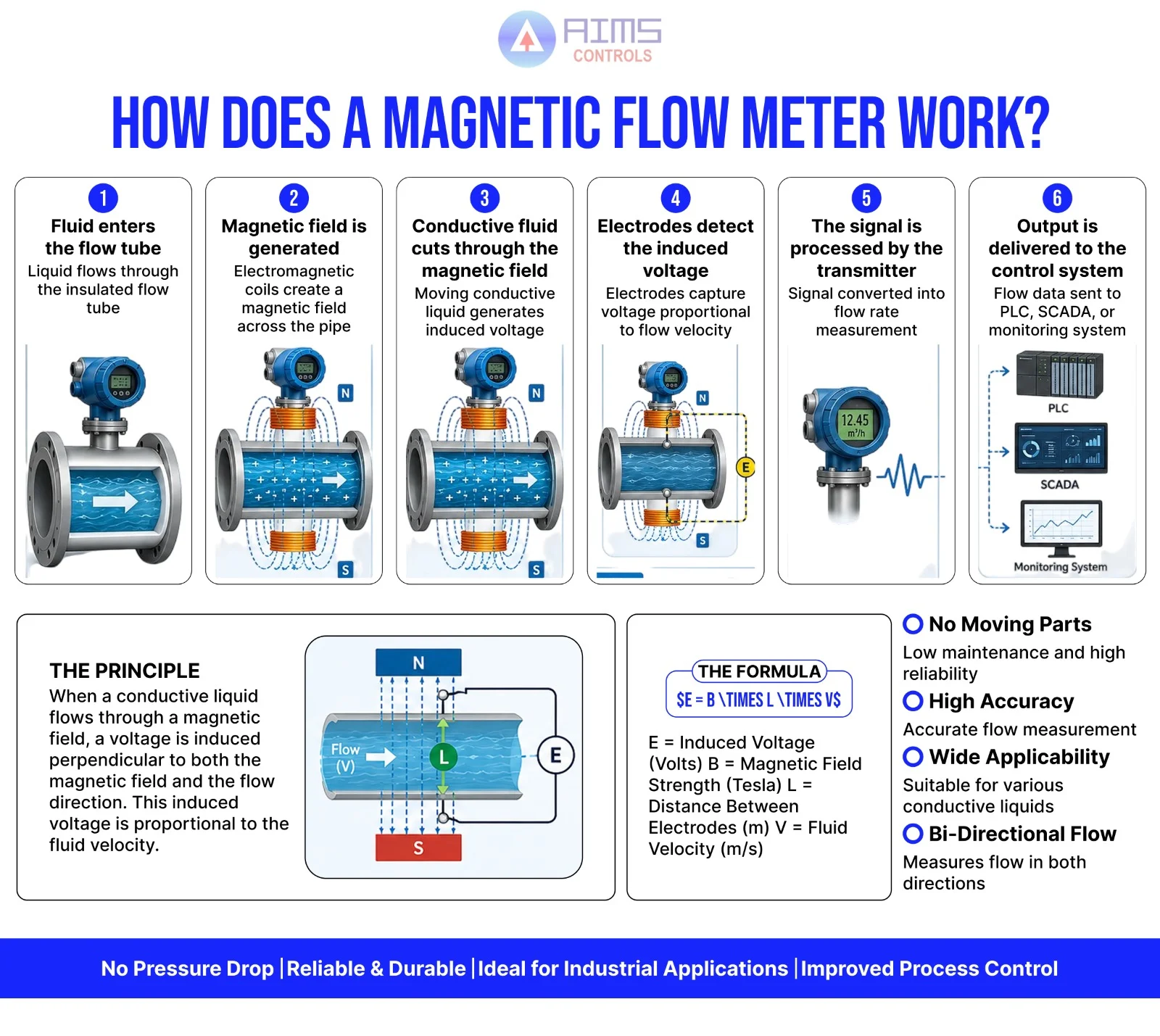
Understanding how a magnetic flow meter works is straightforward when broken down into sequential steps. Here is the complete working process from fluid entry to flow rate output:
- Fluid enters the flow tube – Conductive liquid flows into the metering section through a non-magnetic, non-conductive lined tube that prevents the meter body from interfering with the magnetic field or electrical signal.
- A magnetic field is generated – Electromagnetic coils wound around the outside of the flow tube are energized by an alternating or pulsed DC from the transmitter. This creates a controlled magnetic field perpendicular to the direction of fluid flow.
- Conductive fluid cuts through the magnetic field – As ions and charged particles in the moving liquid cross the magnetic field lines, they experience a Lorentz force that pushes positive ions toward one electrode and negative ions toward the other.
- Electrodes detect the induced voltage – Two electrodes, flush-mounted or protruding into the bore on opposite sides of the pipe, sense the tiny voltage differential generated by the flowing liquid. The faster the fluid moves, the greater the induced voltage.
- The signal is processed by the transmitter – Transmitter amplifies and filters the raw millivolt signal, applies the calibration constants (B and L from the meter design), and calculates the real-time volumetric flow rate.
- Output is delivered to the control system – Transmitter provides a 4-20 mA analogue output, HART digital signal, Modbus, or pulse output to SCADA systems, PLCs, or data loggers for monitoring and control.
This entire process happens continuously in real time, with modern instruments updating the flow reading multiple times per second. The result is a stable, noise-free flow signal even in turbulent or fluctuating flow conditions.
Components of a Magnetic Flow Meter
Every electromagnetic flow meter consists of a small number of carefully engineered components. Understanding each part helps in selecting the right instrument for any industrial application.
- Flow Tube: The primary measurement section where the fluid flows. Constructed from non-magnetic metals (stainless steel, carbon steel) to avoid interference with the magnetic field. The tube bore determines the meter size and flow range.
- Liner: An internal insulating coating applied to the flow tube bore that electrically isolates the fluid from the metal body and protects against corrosion, abrasion, and chemical attack. Common materials include polyurethane (for abrasive slurries), PTFE (for aggressive chemicals and high temperatures), neoprene, and hard rubber (for general water applications).
- Electromagnetic Coils: Two opposing coils energized by the transmitter to produce the magnetic field across the pipe bore. The coil design and power supply determine field strength (B), which is held constant throughout measurement.
- Electrodes: Two (sometimes more) sensing elements mounted flush with or protruding slightly into the liner on opposite sides of the tube. They detect the induced voltage signal directly from the fluid. Electrode materials, such as stainless steel, Hastelloy, titanium, and platinum, are chosen based on fluid chemistry and temperature.
- Transmitter / Signal Converter: The electronics package that powers the coils, amplifies the electrode signal, applies calibration algorithms, and produces standardized output signals (4-20 mA, HART, pulse, Modbus). May be integral to the flow tube or remotely mounted up to 100 m away. You can also understand the difference between related instruments in this guide on flow meter vs flow transmitter vs flow switch.
- Display and Communication Interface: Local LCD or LED displays show real-time flow rate and totalized volume. Communication ports support integration with DCS, SCADA, and asset management systems.
Material selection, particularly for the liner and electrodes, is critical for long service life and measurement reliability. Always match materials to the fluid’s temperature, pressure, pH, and abrasive content when sourcing flow instrumentation.
Advantages of Magnetic Flow Meters
The enduring popularity of the magnetic flow meter across industries is driven by a set of performance advantages that few other flow technologies can match:
- No Moving Parts: The absence of internal mechanical components eliminates the risk of wear, fatigue, and mechanical failure, dramatically extending instrument life and reducing unplanned downtime.
- High Accuracy: Typical accuracy of ±0.2-0.5% of reading across a wide flow range (turndown ratios up to 100:1) makes magmeters suitable for custody transfer and precision process control applications.
- Zero Pressure Drop: The full-bore, unobstructed flow path introduces no additional resistance to the fluid, reducing pumping costs and protecting fluid integrity in sensitive applications like food processing.
- Low Maintenance: With no wearing components, maintenance requirements are limited to periodic electrode cleaning (in fouling applications) and transmitter calibration checks.
- Bi-directional Measurement: Magmeters can measure forward and reverse flow without any modification, making them useful in applications like water network management, where flow direction can change.
- Handles Difficult Fluids: Unlike most flow technologies, magnetic flow meters perform reliably with slurries, sewage, pulp, and highly viscous liquids that would damage or block mechanical meters.
- Corrosion Resistance: With appropriate liner and electrode materials, magmeters can measure highly aggressive acids, alkalis, and saline solutions without instrument degradation.
- Wide Temperature and Pressure Range: Standard models handle temperatures up to 180°C and pressures up to 40 bar, with special designs available for extreme conditions.
Limitations of Magnetic Flow Meters
Understanding the limitations of magnetic flow meters is equally important for making the right instrument selection. A transparent assessment builds buyer confidence and ensures the instrument performs as expected in the field.
- Conductive Fluids Only: Magnetic flow meters require the process fluid to have a minimum electrical conductivity, typically 5 µS/cm or higher. This excludes measurement of hydrocarbons (oil, fuel, solvents), most gases, and ultrapure DI water (conductivity < 0.5 µS/cm).
- Cannot Measure Gases or Steam: The electromagnetic induction principle only works with liquid conductors. For gas, steam, or multiphase flow, alternative technologies such as vortex or Coriolis meters must be used.
- Higher Initial Cost: Compared to simple mechanical meters, magmeters carry a higher upfront cost. However, their long service life and near-zero maintenance costs typically result in a lower total cost of ownership over 10-15 years.
- Pipe Must Run Full: Magnetic flow meters require a full pipe for accurate measurement. Partially filled pipes introduce air gaps that interrupt the electrode signal and produce erroneous readings.
- Installation Space: Accurate measurement requires straight pipe runs typically 5-10 pipe diameters upstream and 3 diameters downstream, free from elbows, valves, or other flow disturbances.
These limitations are well understood in industry, and the applications where magnetic flow meters do excel far outnumber those where they cannot be used. Explore AIMS Controls products to find the right flow solution for your specific fluid and process conditions.
Magnetic Flow Meter Applications
The magnetic flow meter application range spans virtually every industry that handles conductive liquids. Here is where these instruments deliver the most value:
Water Treatment and Distribution
Municipal water treatment plants rely on magnetic flow meters for accurate measurement of raw water intake, chemical dosing flows, filter backwash, and distribution network monitoring. Their ability to handle water with suspended solids and varying conductivity makes them the standard instrument of choice.
Wastewater and Sewage Management
Magnetic flow meters excel in wastewater applications because they tolerate fibrous materials, grit, sludge, and highly variable fluid compositions without fouling or measurement degradation. They are used for influent and effluent flow monitoring and regulatory compliance reporting.
Chemical Processing
With appropriate liner and electrode materials (PTFE liner, Hastelloy or titanium electrodes), magmeters measure corrosive acids, alkalis, and solvent-based mixtures with high accuracy and long service life. They are integral to reactor feed control, product flow totalization, and blending systems.
Food and Beverage
In hygienic processes, dairy, beverages, sauces, and edible oils, magnetic flow meters with PTFE liners, polished stainless steel electrodes, and sanitary fittings meet strict FDA and EHEDG hygiene standards. Their full-bore, crevice-free design supports clean-in-place (CIP) and steam-in-place (SIP) procedures.
Pharmaceutical Manufacturing
Pharmaceutical-grade processes require meticulous flow accuracy and complete hygienic integrity. Magmeters deliver validated, repeatable measurements for WFI (water for injection), process water, and CIP solution flows with FDA 21 CFR Part 11-compatible transmitters available for data integrity compliance.
Mining and Mineral Processing
Magnetic flow meters with polyurethane or ceramic liners and hard-faced electrodes withstand the highly abrasive slurries of ore processing, tailings transport, and mineral concentration circuits where mechanical meters would fail within weeks.
Pulp and Paper
Cellulose pulp, white water, black liquor, and chemical recovery streams are all effectively measured using magmeters. The instruments tolerate the high solids content and pH extremes common in pulping and bleaching processes.
HVAC and Building Services
Energy monitoring in heating and cooling circuits, especially in large commercial and industrial buildings, uses magnetic flow meters to measure chilled water and hot water flows for heat energy (BTU) calculations. This data supports building management system (BMS) optimization and energy billing across various industrial applications.
Magnetic Flow Meter vs Other Flow Meters
Choosing the right flow technology requires a clear understanding of how each option performs across the factors that matter most in your application. The table below compares magnetic flow meters against ultrasonic, turbine, and vortex alternatives.
| Parameter | Magnetic | Ultrasonic | Turbine | Vortex |
| Accuracy | ±0.2-0.5% | ±1-2% | ±0.5-1% | ±0.5-1% |
| Moving Parts | None | None | Yes | None |
| Pressure Drop | Very low | Very low | Moderate | Moderate |
| Conductive Fluid Req. | Yes | No | No | No |
| Maintenance | Very low | Low | High | Low |
| Bi-directional Flow | Yes | Yes | No | No |
| Suitable for Slurries | Yes | Limited | No | Limited |
| Best Application | Water, chemicals, food | Non-conductive liquids | Clean liquids, fuel | Steam, gas, clean liquid |
Magnetic flow meters are the preferred choice when the fluid is conductive, pressure drop cannot be tolerated, or the process involves slurries or chemically aggressive liquids. For non-conductive fluids such as oils, fuels, and gases, ultrasonic or vortex technologies are more appropriate.
How to Choose the Right Magnetic Flow Meter
Selecting the correct electromagnetic flow meter requires careful evaluation of several process and installation parameters. Rushing this decision leads to measurement errors, premature instrument failure, or unnecessary cost.
- Pipe Size and Flow Range: Magmeters are available from DN3 (1/8″) to DN3000 (120″) bore sizes. Select a size where normal flow falls within the instrument’s optimum operating range (typically 20-80% of full scale for best accuracy).
- Fluid Conductivity: Verify that the process fluid’s conductivity exceeds the meter’s minimum specification (usually 5 µS/cm). For borderline fluids like ultrapure water, request conductivity verification tests or consider a different technology.
- Process Temperature and Pressure: Confirm that the selected liner material and meter body rating are compatible with maximum process temperature and line pressure, including pressure spikes and thermal cycling.
- Liner Material: Match liner to the fluid: rubber or polyurethane for abrasive slurries, PTFE for aggressive chemicals and high temperatures, neoprene for general water and mild process fluids.
- Electrode Material: Standard 316L stainless steel suits most water applications. Hastelloy C offers superior corrosion resistance for chlorides and oxidizing acids. Titanium suits seawater and marine applications. Platinum is used in pharmaceutical and high-purity applications.
- Installation Orientation and Space: Magnetic flow meters can be installed horizontally, vertically (upward flow preferred to ensure full pipe), or at any angle. Always maintain the required upstream/downstream straight pipe run lengths for accurate measurement.
- Output and Communication Protocol: Confirm that the transmitter’s output signal (4-20 mA, HART, Profibus, Modbus, pulse) is compatible with your DCS or PLC system before ordering.
- Hazardous Area Classification: For installations in explosive atmospheres (ATEX, IECEx zones), select a meter with the appropriate ignition protection certification.
Working with an experienced instrumentation supplier ensures that all these factors are evaluated correctly the first time.
FAQs
1. What is the principle of a magnetic flow meter?
A magnetic flow meter operates on Faraday’s Law of Electromagnetic Induction. When conductive fluid flows through a magnetic field generated by coils in the meter, a voltage is induced proportional to the fluid’s velocity. Electrodes detect this voltage, and the transmitter converts it into a calibrated volumetric flow rate. The formula is E = B × L × V.
2. How does a magnetic flow meter work?
Electromagnetic coils create a magnetic field across the flow tube. As conductive liquid flows through, ions in the fluid separate under the Lorentz force, generating a voltage detected by electrodes. The transmitter amplifies this signal, applies calibration constants, and outputs a real-time flow rate to connected control systems, all with no moving parts.
3. What liquids can magnetic flow meters measure?
Magnetic flow meters measure any electrically conductive liquid with conductivity typically above 5 µS/cm. This includes water, wastewater, sewage, acids, alkalis, slurries, food-grade liquids, and pharmaceutical process fluids. They cannot measure gases, steam, hydrocarbons (oil, fuel, solvents), or ultrapure deionized water with very low conductivity.
4. Where are magnetic flow meters used?
Magnetic flow meter applications span water treatment, wastewater management, chemical processing, food and beverage production, pharmaceutical manufacturing, mining and mineral processing, pulp and paper, and HVAC energy metering. Any industry that handles conductive liquids and requires accurate, low-maintenance flow measurement benefits from electromagnetic flow technology.
5. What are the advantages of magnetic flow meters?
Key advantages include: no moving parts (long service life), high accuracy (±0.2-0.5%), zero pressure drop, bidirectional measurement capability, suitability for slurries and corrosive fluids, and low maintenance requirements. Their full-bore design handles difficult fluids that would damage or block mechanical meters, making them a highly cost-effective long-term investment.
Conclusion
The magnetic flow meter principle, electromagnetic induction via Faraday’s Law, delivers a simple yet powerful measurement solution for conductive liquid flow. With no moving parts, high accuracy, zero pressure drop, and compatibility with a wide range of challenging fluids, magmeters have earned their place as the go-to instrument across water, chemical, food, pharmaceutical, and industrial process applications.
From understanding the core magnetic flow meter working principle to navigating liner and electrode selection, accurate flow measurement starts with choosing the right instrument for your specific process. The magnetic flow meter application range continues to expand as industries prioritize reliability, efficiency, and sustainability.
AIMS Controls offers a comprehensive range of electromagnetic flow meters designed for demanding industrial environments. Contact the team or get a quote to find the right flow meter for your application.