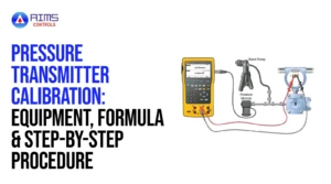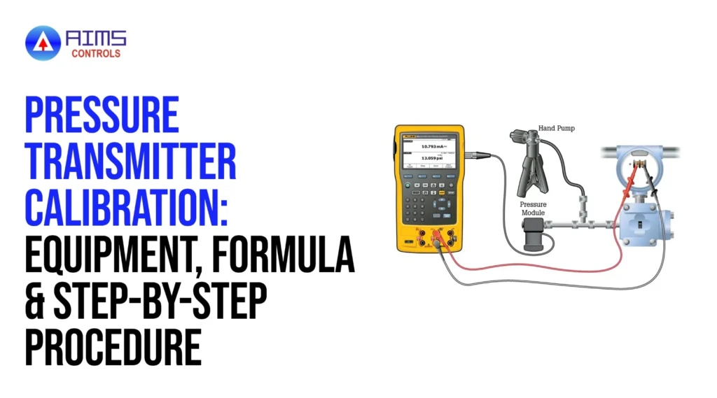
A pressure transmitter that drifts by even a small amount can throw off a control loop, waste product, or hide a safety problem. Calibration is how you find that drift and correct it before it matters. This guide explains how pressure transmitter calibration works in practice: the specifications to check, the equipment you need, the 4-20 mA formula, a worked example, a step-by-step procedure, and the difference between simply checking a transmitter and adjusting it.
What Is Pressure Transmitter Calibration?
Pressure transmitter calibration compares a transmitter’s output with a known reference pressure at several points across its range, then corrects the device if the error exceeds the allowed tolerance. The reference standard must be more accurate than the transmitter, ideally by a ratio of 4:1 or better.
To understand why a transmitter drifts, it helps to know the pressure transmitter working principle: a sensing element converts pressure into a small electrical signal, and the electronics turn that signal into a standard output such as 4-20 mA. Calibration confirms that this whole chain, from sensor to output, still behaves correctly.
Two terms are used throughout the procedure:
- LRV (lower range value): the pressure that should produce 4 mA, usually 0.
- URV (upper range value): the pressure that should produce 20 mA.
- Span: URV minus LRV.
Calibration Check vs. Adjustment
These two activities are often confused, but they are not the same.
A calibration check applies known pressures and records what the transmitter outputs, without changing anything. These readings are the as-found data. If every point is within tolerance, no adjustment is needed.
An adjustment (trim) changes the transmitter’s internal settings to remove the error. After adjusting, you repeat the test and record the as-left data. Adjusting a transmitter that is already within tolerance adds no value and can introduce new error, so always check first.
Check Transmitter Specifications
Before connecting any equipment, read the nameplate and datasheet. You need to know:
- Calibrated range (LRV and URV) and the maximum working pressure
- Pressure type, including gauge and absolute pressure, because an absolute transmitter reads about 1.01 bar at atmospheric pressure and cannot be zeroed by venting to a 0 reference
- Accuracy, stated as a percentage of span or reading
- Output signal and communication protocol, such as 4-20 mA with HART
- Supply voltage and allowable loop resistance
- Process connection and any required diaphragm seal
The accuracy figure sets your acceptance tolerance. For example, a transmitter rated at ±0.075% of span on a 0-10 bar range must be correct to within ±0.0075 bar, or ±0.012 mA.
Calibration Equipment Required
The equipment must be traceable to a recognised standard and within its own calibration date. Checking pressure gauge accuracy against the same reference is a useful way to confirm the reference itself is healthy before you start.
| Equipment | Purpose |
| Pressure calibrator or hand pump with reference gauge | Generates and measures known pressure |
| Precision mA meter or loop calibrator | Measures the transmitter’s output current |
| 24 V DC power supply | Powers the loop if no control system is connected |
| HART communicator or configuration software | Reads and changes transmitter settings |
| 250 Ω loop resistor | Allows HART communication on a bench setup |
| Fittings, adapters, and leak-test fluid | Connects the transmitter without leaks |
| Calibration record sheet | Records as-found and as-left data |
Safety and Preparation
Follow your site’s permit and isolation rules, and the manufacturer’s manual, before starting.
- Notify operations and place the control loop in manual so the output cannot trigger a process action.
- Isolate the transmitter from the process and relieve trapped pressure safely.
- Check for hazardous area requirements, and use only approved test equipment in classified zones.
- Let the transmitter stabilise at ambient temperature for several minutes.
- Inspect the diaphragm, fittings, and wiring for damage or moisture.
Pressure Transmitter Calibration Methods
The method depends on the transmitter type and the site setup.
- Bench calibration: The transmitter is removed and tested in a workshop. Conditions are controlled, and results are repeatable, but the effect of mounting position is not captured.
- In-situ (field) calibration: The transmitter stays installed and is tested through a test port or isolation manifold. It is faster and avoids disturbing the process connection.
- Loop calibration: Apply pressure at the transmitter while confirming the reading in the control system or recorder, validating the entire signal path.
Whichever method you choose, the same principles apply. If you need a replacement or a new device with a suitable range, you can compare available pressure transmitters by range, accuracy, and output type.
The 4-20 mA Calibration Formula
For a linear transmitter, 4 mA represents the bottom of the range and 20 mA the top. The span of the current signal is 16 mA, so:
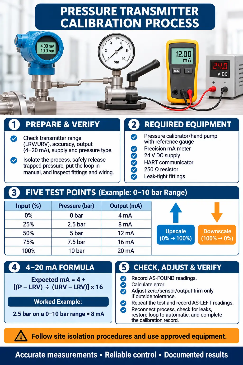
Expected output (mA) = 4 + [(P − LRV) ÷ (URV − LRV)] × 16
To work backwards from a measured current to pressure:
Pressure = LRV + [(I − 4) ÷ 16] × (URV − LRV)
Worked Example: 0-10 bar Transmitter
For a transmitter ranged 0-10 bar, the expected output at 2.5 bar is:
4 + (2.5 ÷ 10) × 16 = 4 + 4 = 8 mA
The table below lists the standard five-point test.
| Input (%) | Pressure (bar) | Expected output (mA) |
| 0 | 0 | 4.00 |
| 25 | 2.5 | 8.00 |
| 50 | 5.0 | 12.00 |
| 75 | 7.5 | 16.00 |
| 100 | 10.0 | 20.00 |
Now suppose the transmitter reads 12.06 mA when exactly 5 bar is applied. The error is:
(12.06 − 12.00) ÷ 16 × 100 = 0.375% of span
Against a tolerance of ±0.075%, this point fails, and the transmitter needs adjustment.
Step-by-Step Calibration Procedure
- Record the details – Note the tag number, serial number, range, calibrator ID, and ambient conditions.
- Connect the equipment – Wire the mA meter in series with the loop, connect the pressure source to the transmitter port, and make sure all fittings are leak-tight.
- Vent and stabilise – With the transmitter open to atmosphere (gauge types), confirm the output is close to 4 mA. For absolute types, apply a vacuum or reference pressure instead.
- Run the as-found test – Apply 0, 25, 50, 75 and 100% of range, then return through 75, 50, 25 and 0%. Wait for the reading to settle at each point, and record pressure and mA.
- Calculate errors – Compare each reading with the expected value and convert to percent of span.
- Decide whether to adjust – If all points are within tolerance, document the result and stop. If not, continue to the adjustment steps below.
- Adjust the transmitter – Apply the correct trim procedure, as described in the next section.
- Run the as-left test – Repeat the full up-and-down sequence and record the final results.
- Restore the loop – Remove the test equipment, reconnect the process, check for leaks, return the loop to automatic, and complete the calibration certificate.
Zero and Span Adjustment
Smart transmitters offer several kinds of adjustment, and choosing the right one matters.
- Zero trim: Corrects the offset at zero pressure. It is the most common adjustment and compensates for mounting position or small drift. Apply a known zero (or the LRV) and trim the reading to match.
- Sensor (lower and upper) trim: Applies two known pressures near the ends of the range so the sensor’s digital reading matches the reference. This corrects both offset and slope of the sensor itself.
- 4-20 mA output trim: Corrects the digital-to-analogue stage so that the output current reads exactly 4.00 and 20.00 mA when commanded. Use it when the sensor reading is correct, but the analogue output is off.
- Range change (LRV/URV setting): Redefines which pressures correspond to 4 and 20 mA. This changes the scale, not the accuracy.
As a rule, correct the sensor first, then the output. Smart pressure transmitters allow all of these changes through HART, while older analogue models use zero and span potentiometers. Make small changes, apply the pressure, and verify before moving on.
Calculating Error and Acceptance
For each test point, use:
Error (% of span) = [(Measured mA − Expected mA) ÷ 16] × 100
Check the following against the datasheet tolerance:
- Zero and span error: the deviation at 0% and 100%
- Linearity: the deviation at the middle points
- Hysteresis: the difference between upscale and downscale readings at the same pressure
- Repeatability: the spread when the same point is applied more than once
The transmitter passes only if every point, in both directions, falls within tolerance.
Common Calibration Errors and Causes
| Symptom | Likely cause |
| Constant offset at all points | Zero shift, mounting position, or trapped head pressure |
| Error increases with pressure | Span or slope error |
| Large gap between up and down readings | Hysteresis, sensor damage or leaks |
| Unstable readings | Leaking fitting, vibration, or temperature change |
| Output stuck or out of range | Wiring fault, wrong range setting, or failed electronics |
How Often Should You Calibrate?
There is no single interval. Set it using the manufacturer’s stability specification, how critical the loop is, and the drift seen in records. Many plants start at twelve months and lengthen or shorten the interval based on as-found results. Also recalibrate after overpressure events, repairs, or sensor replacement.
Frequently Asked Questions
1. What is pressure transmitter calibration?
It is comparing the transmitter’s output with a known reference pressure at several points, then correcting the device if errors exceed the allowed tolerance.
2. How often should a pressure transmitter be calibrated?
Most plants calibrate annually, but critical loops may need six-month checks. Follow manufacturer guidance, process risk, regulatory needs, and the drift shown in previous calibration records.
3. What is the 4-20 mA calibration formula?
Expected current equals 4 mA plus the fraction of span applied multiplied by 16 mA, where the fraction is (pressure − LRV) divided by (URV − LRV).
4. What equipment is needed for calibration?
You need a pressure calibrator or pump with a reference gauge, a precision mA meter, a 24 V supply, a HART communicator, and the correct fittings.
5. What is the difference between a calibration check and an adjustment?
A check records as-found errors without changing anything. An adjustment, or trim, changes the transmitter’s settings to correct those errors, and the results are recorded as as-left data.
6. How many calibration points should I use?
Use at least five points, typically 0, 25, 50, 75, and 100 percent, applied upscale and downscale. This reveals linearity errors and hysteresis.
7. Can I calibrate a transmitter without removing it from the process?
Yes, if the loop has isolation and test valves or a vent port. Otherwise, remove the transmitter, since applying reference pressure through process lines risks errors and contamination.
8. What causes pressure transmitter drift?
Common causes include temperature changes, overpressure, vibration, sensor aging, moisture ingress, and mounting position changes. Regular calibration records help identify drift trends early.
9. What is an acceptable calibration error?
It depends on the datasheet accuracy and process needs. Many plants set tolerance at the stated accuracy, such as ±0.075% of span, or tighter for critical loops.
10. Why is a 250-ohm resistor needed for HART calibration?
HART communication needs at least 250 ohms of loop resistance. Without it, the communicator cannot read the digital signal reliably, even though the 4-20 mA output still works.
Keep Pressure Measurements Accurate and Reliable
Accurate pressure transmitter calibration requires the right equipment, a proper testing procedure, and careful verification of output readings. Regular calibration helps detect measurement drift, reduce errors, and maintain consistent process performance.
Before your next calibration, review the pressure transmitter working principle to understand how pressure changes affect output signals. Then check your transmitter’s zero and span settings, verify the 4-20 mA readings, and document the results to ensure reliable pressure measurements.